Merrill Dougherty and David Finley. Cast-in-place reinforced concrete box culverts have been designed and used for many years because of special waterway requirements unusual load conditions or designer preference.

Design Draw A Pipe Culvert With 3 Vents Examples Part 1 Youtube
Calculate the culvert design flows Section 3-31 2.
. 272 DESIGN CONSIDERATIONS 2721 Headwater Any culvert that constricts the natural stream flow will cause a rise in the upstream water surface. The result is a comprehensive culvert design publication. Culvert hydrology and hydraulic calculations as described in Section 3-3 and Table 3-2.
A cast in- situ headwall extension with minimum thickness as specif ied in the standard drawing 1243 Drawing 2 and 3 shall be used to connect the precast headwall and the pipe or box culvert. Working Guide to Pump and Pumping Stations. Velocity of flow through pipe.
958 Culvert Design Form 9-43 96 DESIGN EQUATIONS 9-34 961 General 9-34 962 Approach 9-34 963 Inlet Control 9-34. Hydraulic Design series No. Pipe Culverts Page 27 Design Example Inlet Type 3.
The minimum diameter of culvert pipes under a main roa dway shall be 18 inches. From the Solve For list select the value that you want to calculate. Hydrologic analysis methods are described and references cited.
42 Structural Design of Culverts 421 Introduction Structural design of a culvert must be performed to ensure that the culvert is strong enough to resist the loads that will be imposed upon it. The distribution of live loads for fills 2 feet shall be according to Article 46210 and for fills. Examples of flexible pipes are plastic and thin walled metal pipes.
5 combines culvert design information previously contained in Hydraulic Engineering Circulars HEC No. Mannings n 0024. If only the design peak discharge is used in the design the engineer cannot assess what effect increases in the essential design discharge will have on the culvert design.
Circular pipe culverts are widely used in transportation applications to transport stormwater under roadways railways etc. The American Concrete Pipe Associations precast concrete box section program was implemented to develop a product for these applications and. Culvert pipe under roadway approaches ie driveway shall have.
Design Data print and use as a checklist Having this design data will get you through the design review part of a spot check 1. Use type 3 transition Fig. Highway authorities may have different or additional requirements which are not discussed herein.
But remember to always check your results. The actual headwall extension dimensions shall be determined to suit the project specific culvert. For example a circular shape.
A is the cross-sectional area of the culvert in ft2 m2 for SI. The primary objective of a culvert or bridge is to convey stormwater flows based on a design flow rate through. Culverts diameter or height greater than 1200.
Bed level of flow. DATA Discharge through pipe culvert. Sometimes a small increase in flow rate can affect a culvert design.
Determine the type of control that exists at the design flows either inlet control or outlet control Section 3-34 5. HW is the headwater depth above the invert at the inlet in ft m for SI. Using HY-8 to Design Culverts LETS TRY A DESIGN EXAMPLE.
13 with hydrologic storage routing and special culvert design information. Box Culvert - A culvert in the shape of an enclosed rectangle and consisting of a bottom slab two wall elements and a top slab. Advanced Design Examples of Seismic Retrofit of Structures.
Pipe Culvert Interior Designation Smooth Interior. Click on Load button to load an existing culvert file to view or modify it or a new file to start a fresh design. The parameters in the equation are as follows.
It is the structural element that allows the movement of the vehicles. Culvert Extension - A portion of a culvert built beyond the limits of a previously existing culvert. Proposed roadway stationing of the culvert location.
From the Structure menu in the Hydrology Module choose Pipe Culvert Design to display the design dialog. DRAINAGE CRITERIA MANUAL BRIDGE AND CULVERT HYDRAULIC DESIGN City of Bella Vista AR CB-1 10 CULVERTS INTRODUCTION AND OVERVIEW The purpose of this chapter is to provide guidance for culvert and bridge hydraulic design. Major design parameters for culvert design are the diameter and slope of the pipe for a specified culvert material.
An example of the latter method is a nomograph developed by California and shown in Figure 27. The strength of a culvert depends on the strength of the materials that are used and the shape of the culvert barrel. Mannings n 0012 Corrugated Interior.
Culvert Manual CM 34 - LRFD Culvert Design Loads May 2019 Page 5 According to Article 121121 live load distribution is dependent on fill height. The emphasis in this Chapter is on the design of culverts for urban stormwater drainage. The Basics of Culvert and Inlet Design Introduction The design of a culvert is influenced by cost hydraulic efficiency purpose and the topography at the proposed culvert site.
Thus physical data must be integrated with engineering and economic considerations. 3 7 6 w 6 6 B ft L ft inches t inches H ft Page 28 Design Example Pipe Friction. As per the nature of the structure the following components included in a box culvert.
The proof is in the pictures of this brochure that show jetting or collapse of high density polyethylene culverts and the roadways because of flotation. This brochure explains the average density of concrete pipe as compared to corrugated PE pipe. Discharge Headwater and Size.
5000 package of 25. Culvert Design Part I Author. Q is the design discharge through the culvert in cfs m3s for SI.
D is the inside height of the pipe culvert in fr m for SI. Flexible Pipe - a structure that transmits the load on the pipe to the soil at the sides of the pipe. Determine the tailwater elevation at the design flow Section 3-33 4.
C h a p t e r 9 ²C u l v e r t s 9-5. Part 1 In this video we will learn how to design and draw a pipe culvert with 3 vents for section elevation and Plan half earth removed sectionsIf you have. 2500 package of 25.
Box culvert is a rectangular shape reinforced concrete structure consists of single or multiple boxes allowing movement of water and traffic. Determine the allowable headwater elevation Section 3-32 3. Inlet type As the drainage channel is poorly defined and the upper canal bank is only 4 ft higher than channel invert a type 3 or 4 inlet transition will be good.
DESIGN OF PIPE CULVERT. General Culvert Design Method 1. The site and any possible hazards.
Corrugated metal and concrete are used for many of these pipe culverts. The available values are. Designer - Individuals designated by the Structural Engineer to use this manual to design and detail culverts.

Pipe Culverts Specification And Drawing Youtube
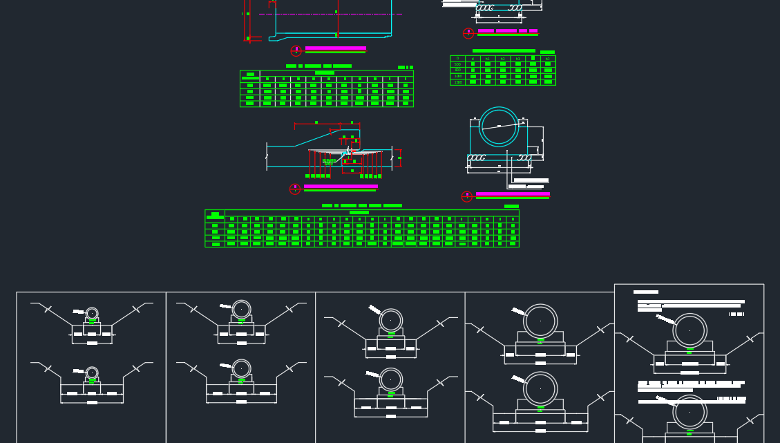
Pipe Culvert Details Autocad Drawing

Typical Configuration Of A Corrugated Steel Pipe Arch Culvert 1 Download Scientific Diagram

Pipecar American Concrete Pipe Association

Recommendations For Design Of Reinforced Concrete Pipe Journal Of Pipeline Systems Engineering And Practice Vol 1 No 1

Culvert An Overview Sciencedirect Topics

Recommendations For Design Of Reinforced Concrete Pipe Journal Of Pipeline Systems Engineering And Practice Vol 1 No 1

Construction Methodology Of Pipe Culvert Civilyard
0 comments
Post a Comment